Vitodens 200-W B2KA 3.2 to 35 kW
Vitodens 200-W B2KA 3.2 to 35 kW
| ID | Parts Number | Part Description | Notes | Purchase |
|---|---|---|---|---|
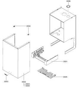
| 1 | Control unit support | |||
| 2 | Front panel | |||
| 3 | Viessmann logo | |||
| 4 | Fixing clip (2 pce) | |||
| 5 | Safety guard | |||
| 6 | Diaphragm grommet DN 60 | |||
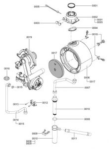
| 1 | Gasket DN 60 | |||
| 2 | Boiler flue connection 60/100 | |||
| 3 | Boiler flue connection plug | |||
| 4 | Flue gasket | |||
| 5 | Flue gas temperature sensor | |||
| 6 | Heat exchanger | |||
| 7 | Condensate hose | |||
| 8 | O-ring 35.4 x 3.6 (5 pce) | |||
| 9 | Locking clip, condensate hose | |||
| 10 | Siphon | |||
| 11 | Condensate hose | |||
| 12 | Gas supply pipe retaining clip | |||
| 13 | Cheese head screw M 6 x 16 (5 pce) | |||
| 14 | Gas supply pipe | |||
| 15 | Gas pipe gasket | |||
| 16 | Diaphragm grommet Ø 54/18 | |||
| 17 | Thermal insulation block | |||
| 18 | Heat exchanger mounting (set) | |||
| 19 | Matrix cylinder burner | |||
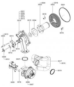
| 1 | Burner gasket (wearing part) | |||
| 2 | Thermal insulation ring | |||
| 3 | Cylinder burner gauze assembly | |||
| 4 | Burner gauze assembly gasket | |||
| 5 | Ignition electrode (wearing part) | |||
| 6 | Ionisation electrode (wearing part) | |||
| 7 | Burner door flange gasket (wearing part) | |||
| 8 | Radial fan | |||
| 9 | Gas train | |||
| 10 | Burner door | |||
| 11 | Ignition unit | |||
| 12 | Ionisation electrode gasket (5 pce) | |||
| 13 | Ignition electrode gasket (5 pce) | |||
| 14 | Blade terminal | |||
| 15 | Mixture restrictor | |||
| 16 | Gas nozzle ? 19 kW: 02 yellow ? 26 kW: 04 grey ? 35 kW: 06 black | |||
| 17 | Venturi extension | |||
| 18 | Mounting plate, thermal insulation ring (2 pce) | |||
| 19 | Gasket DN 65 | |||
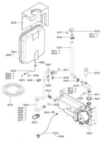
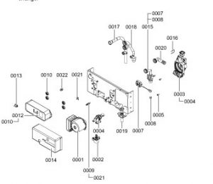
| 1 | Expansion vessel | |||
| 2 | Expansion vessel support | |||
| 3 | Connection line, expansion vessel | |||
| 4 | Clip Ø 8 (5 pce) | |||
| 5 | Thermal circuit breaker | |||
| 6 | Gasket set A 10 x 15 x 1.5 | |||
| 7 | Temperature sensor | |||
| 8 | Air vent valve G 3/8 | |||
| 9 | Heat exchanger connection pipe | |||
| 10 | Drain hose 10 x 1.5 x 1500 | |||
| 11 | O-ring 20.6 x 2.6 (set) | |||
| 12 | Diaphragm grommet | |||
| 13 | Plug-in connector retainer (set) | |||
| 14 | Pressure gauge | |||
| 15 | Heating water return connection elbow | |||
| 16 | Hose clip DN 25 | |||
| 17 | Heating water return connection pipe | |||
| 18 | Heating water return connection elbow | |||
| 19 | Quick-action air vent valve G 3/8 | |||
| 20 | Locking pin | |||
| 21 | Diaphragm grommet | |||
| 22 | Plug-in connector gasket (set) | |||
| 23 | Round sealing ring 8 x 2 (5 pce) | |||
| 24 | Clip Ø 10 (5 pce) | |||
| 25 | Aqua-plate | |||
| 1 | Circulation pump motor | |||
| 2 | Linear stepper motor | |||
| 3 | Return unit | |||
| 4 | Adaptor for stepper motor | |||
| 5 | Screw 50 x 14 (5 pce) | |||
| 7 | Flow switch | |||
| 8 | Water volume controller | |||
| 9 | Temperature sensor | |||
| 10 | Plate heat exchanger gasket (set) | |||
| 12 | Plate heat exchanger | |||
| 13 | Temperature sensor NTC | |||
| 14 | Thermal insulation, plate heat exchanger | |||
| 15 | Flow switch connection assembly | |||
| 16 | Locking pin Ø 18 (5 pce) | |||
| 17 | Heating water flow connection pipe | |||
| 18 | DHW connection pipe | |||
| 19 | Heating water return connection pipe | |||
| 20 | Plate heat exchanger connection elbow | |||
| 21 | Clip Ø 8 (5 pce) | |||
| 22 | Non-return valve DN 15 | |||
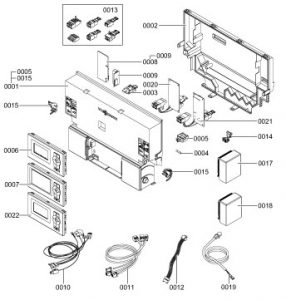
| 1 | Control unit | |||
| 2 | Control unit casing back panel | |||
| 3 | Coding card | |||
| 4 | Fuse 6.3 A (slow) (10 pce) | |||
| 5 | Fuse holder | |||
| 6 | Programming unit for constant temperature mode | |||
| 7 | Programming unit for weather compensated mode | |||
| 8 | LON module | |||
| 9 | PCB adaptor | |||
| 10 | Cable harness X8/X9/ionisation | |||
| 11 | Cable harness 100/35/54/PE | |||
| 12 | Power cable, stepper motor | |||
| 13 | Mating plug (set) | |||
| 14 | Cable fixing | |||
| 15 | Locking bolts, left and right | |||
| 17 | Wireless outside temperature sensor | |||
| 18 | Outside temperature sensor (hardwired) | |||
| 19 | KM BUS connecting cable 145 | |||
| 20 | Internal extension H1 | |||
| 21 | Internal extension H2 | |||
| 22 | Programming unit for room temperature-dependent mode | |||
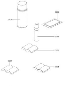
| 1 | Spray paint, Vitowhite | |||
| 2 | Touch-up paint stick, Vitowhite | |||
| 3 | Special grease | |||
| 4 | Installation and service instructions | |||
| 5 | Operating instructions for constant temperature mode | |||
| 6 | Operating instructions for weather compensated mode |